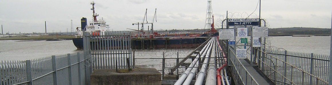
Undetected fuel leaks expose fuel transporters to millions of pounds of unnecessary liability every year. If leaks occur, transporters are faced with expensive repair and clean up costs. Locating where to expose damaged pipes can push the cost even further and the disruptions caused by repairs incur additional costs. But these costs can represent merely the tip of the iceberg as environmental damage and clean up costs also need to be considered. Depending on the situation, local regulatory penalties, especially where drinking water is threatened, could easily exceed any money spent on repairing pipes. And at the very least, the organisation’s reputation as a good neighbour will suffer, potentially threatening future community goodwill and support.
It’s therefore clear that detecting fuel leaks quickly and accurately is of paramount importance. Yet many transporters are still using outdated and expensive systems that often aren’t able to detect leaks effectively within the situations in which they are employed to operate. Indeed, whilst many systems currently available can alert a fuel transporters to the fact that a large leak has occurred or is occurring, little information can be provided if the leak is at a low rate, or indeed where it is.
Commonly, a fuel leak of sufficient size and rate can be detected using modelling techniques that study the pressure and flow of fuel, based on data analysis. This system is often referred to as Scada-based leak detection. The basic concept is to accurately model what the pressure and flow rates in the system should be at any given time and then compare this against real time data. When the real time data drifts from the predicted value the system can then assume a leak is occurring and indicate the extent of the leak. But whilst this approach can indicate the size of the leak, its ability to do so accurately is wholly dependant on the capability to accurately model the fluid dynamics of the piping system. The issue can be accentuated when looking to detect leaks within complex hydrant networks featuring loops, branches, dead legs and lots of valve activity. Another method that can indicate the size of the leak is by using tracer gas. This method involves inoculating the fuel supply with a unique and volatile additive. Soil gases are then sampled at predetermined points and any leaking tracer chemical spreading through the soil will show up distinctly in laboratory tests.
However, whilst it can indicate the existence of the leak, its success is wholly dependant on the frequency of the tests. Also, it can become an expensive method and it can’t precisely indicate the location of the leak. Identifying a section of pipe where leaks are occurring can be accurately defined using hydrostatic pressure testing. This method involves isolating a section of the hydrant system with valves, pressurising the section and then monitoring it to see if that section can hold the pressure. But whilst this method makes it possible to accurately identify that a leak, even a small leak, is occurring within that sub section, it can’t identify where in that sub section the leak is taking place. Neither can it proactively detect the leak as these leaks can only be detected after the test has been performed.
Another popular approach to the problems caused by leaking fuel is to implement double containment pipe. The use of these expensive pipe designs means that any fuel leaking from the central pipe can still be contained within the outer pipe. However, whilst the central focus of this method is to contain, rather than identify fuel leaks, it is possible to detect fuel accumulating in a low point sump. Whilst it’s possible to identify that there is a leak, again it’s impossible to find out where this leak is occurring.
So, while some methods can indicate roughly where the leak is occurring and others can confirm there is a leak, or indicate the size of the leak, these traditional methods do little to enable fuel transporters to quickly recognise a fuel leak is occurring and take appropriate remedial action while the spill is still small. However, advances in leak detection cable technology, which has been employed since the mid 1980s, means this objective can be realised.
The way in which leak detection cables work is similar to that of a very selective sponge that soaks up trace amounts of liquid hydrocarbon causing a physical change in the core of the sensor cable. The cable, manufactured by Tyco Thermal Controls, utilises a hydrocarbon scavenger material. This material makes it possible to install the sensor cable inside of a slotted PVC conduit, which is buried in the backfill with the hydrant piping. Extensive testing has demonstrated that as the leak begins to contaminate the backfill, sufficient fuel is drawn into the slotted conduit by capillary action to initiate leak detection. Approximately one hour after the leak plume makes contact with the conduit, the sensor cable has absorbed sufficient fuel to trigger a leak alarm. The sensor cable is monitored with inexpensive but sophisticated interface modules, and typically a single hydrant loop or several hundred metres of straight pipe can be monitored by a single instrument node. The monitoring system is able to report the leak and can report the location where the fuel was detected, typically within a metre.
The ability to accurately identify leaks also minimises maintenance and repair costs, making it an attractive solution to ensure that transporters and operators can resolve fuel leaks before they become economic and environmental disasters.